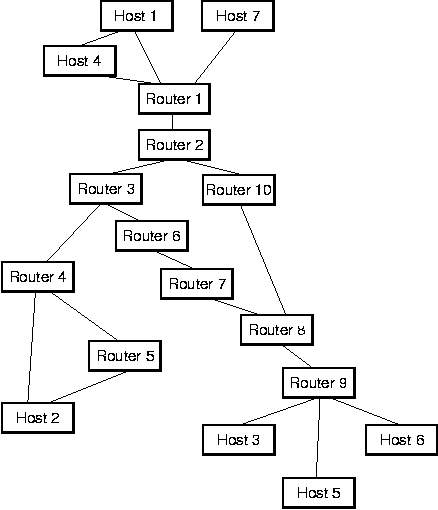
The path abstraction proposed in this dissertation derives from an analogy between communication networks and modular systems. Consider the example communication network depicted in Figure 2. It consists of hosts at the edge of the network and of routers in the interior of the network. The hosts and routers are connected by point-to-point links.

How does a pair of hosts, say host 1 and 3, communicate in such a network? If we assume a datagram-oriented network [100, 76], such as the Internet, then host 1 would prepare a message, append the network address of host 3 to the message, and then inject this datagram into the network by sending it to router 1. Router 1 would forward it to router 2 which has a choice between router 3 and 10. Consulting its routing table, it might decide that router 10 provides a better (e.g., shorter) path to host 3, so it may decide to forward the datagram to router 10. This process continues through router 8 and 9 where the datagram is eventually delivered to host 3.
Purely datagram-oriented networks work fine, but make it difficult to solve certain tasks, such as transmitting data with quality-of-service guarantees such as a maximum latency or a minimum throughput. Also, such networks require a routing decision per router and per packet. If a sequence of packets is transmitted between a pair of hosts, this results in a needlessly large overhead.
An alternative to the datagram style of communication is a connection-oriented style. With a network of this type, if host 1 desires to communicate with host 3, it has to setup a virtual circuit first. It can do so by sending a connection request message to the network which causes the virtual circuit to be established (if possible). Once the virtual circuit exists, host 1 can send data to host 3 simply by injecting messages into the virtual circuit---no address information is required, since all the necessary routing information is already present in the virtual circuit. This means that a routing decision has to be made only once per router, independent of whether one or a million messages are eventually transmitted. In this sense, a virtual circuit can be interpreted as a sequence of fixed routing decisions. Virtual circuits also make it relatively easy to support quality-of-service policies on a per-connection basis. On the negative side, connection-oriented networks require explicit connection setup and tear-down phases (both of which take time) and each virtual circuit ties up some resources in each router (such as memory buffers).

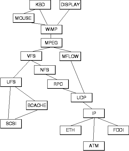
Interestingly, the goals and features of virtual circuits are not unlike those desired for paths. The extra routing overhead in a purely datagram-oriented network loosely corresponds to extra call-overhead in a purely modular system. Similarly, datagram-oriented networks and purely modular systems have difficulty providing quality-of-service guarantees for the same reason: data is processed independently, without regards to the context in which the data appears. Indeed, a modular system can be viewed quite naturally as a network: Figure 3 illustrates a modular system (on a single host) that has a structure that is isomorphic to the communication network shown in Figure 2. In Figure 3, instead of hosts and routers there are modules. The function of these modules is summarized in Table 2. One can see that at the edge of the network are modules that represent devices. For example, module KBD represents a keyboard. Interior modules represent data filters, e.g., MPEG is an MPEG video codec. The modules are connected according to the dependencies between them. For example, as is apparent from the figure, module UFS interacts directly with modules VFS, BCACHE, and SCSI.
| Module: | Description: | Module: | Description: |
| KBD | Keyboard driver | MOUSE | Mouse driver |
| DISPLAY | Graphics adapter driver | WiMP | Window manager |
| MPEG | MPEG codec | VFS | Virtual File System |
| UFS | UNIX File System | BCACHE | Buffer cache |
| SCSI | SCSI driver | MFLOW | Multimedia flowcontrol |
| NFS | Network File System | RPC | Remote Procedure Call |
| UDP | User Datagram Protocol | IP | Internet Protocol |
| ETH | Ethernet driver | ATM | ATM driver |
| FDDI | FDDI driver | ||