[Next] [Previous] [Top]
Development of an Intelligent Monitoring and Control System for a Heterogeneous Numerical Propulsion System Simulation
2. Simulation Strategy
- 2.1 - Zooming
-
- 2.2 - Simulation Tools
-
- 2.3 - Prototype Zooming System
-
The simulation strategy utilizes a high-fidelity flow solver in a low-fidelity simulation, and has been implemented in a prototype zooming framework consisting of the following systems:
- TESS --A propulsion system simulator [12] running with the Application Visualization System (AVS) [1].
- ADPAC --a fully three-dimensional Navier-Stokes/Euler flow analysis package capable of providing detailed flow analysis of the fan component in a turbofan engine [6].
This system is depicted below.
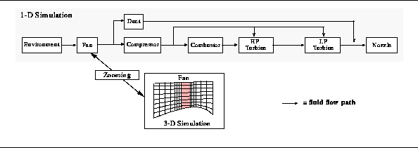
Here the fan component of the one-dimensional "baseline" engine model has been "zoomed" to a three-dimensional analysis.
Implementation of the zooming concept is difficult, due mainly to the inability to accurately resolve high-fidelity data fields from a single value as supplied from the low-fidelity system simulator. In order for the zooming to be accurate, the upstream and downstream boundary values (which are single valued), must be extrapolated to define a suitable three-dimensional distribution of field variables such that when integrated over, the original single-valued boundary conditions are recovered.
This process begins with the single inlet boundary values for stagnation pressure, stagnation temperature, and Mach number, and the exit boundary value of static pressure from the fan component of the one-dimensional engine model. These are then extrapolated to appropriate three-dimensional field distributions and applied as boundary conditions to the fan simulation. The results of the fan 3-D simulation are then integrated to determine the mass-flow rate, and the mass-averaged values of outlet/inlet ratios for the stagnation pressure and stagnation temperature. The averaged stagnation pressure ratio is then compared with the stagnation pressure ratio computed across the engine model. If the values are identical, then the extrapolated field distributions are proved to be suitable representations and the averaged values of mass-flow rate and stagnation temperature ratio may be used in the one-dimensional simulation.
Typically, however, the averaged stagnation pressure ratio will not initially match the low-fidelity simulator value, and the three-dimensional boundary condition representations must be redefined and the above process repeated until the necessary match is found. An iterative approach to boundary value matching was found to be computationally inefficient, requiring many iterations to achieve a balance. Worse, in many instances, the iterative approach led to an oscillatory mode where convergence could not be achieved.
A solution is the construction of a performance map from multiple runs of the three-dimensional component. A single-curve performance map, such as that shown below,
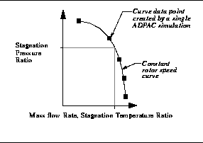
is constructed and the appropriate value can then be chosen from the map, interpolating as needed. To shorten the overall time for the simulation, the multiple runs can be performed in parallel when the necessary computational resources are available.
This section presents an overview of TESS and ADPAC. Also presented is PVM [13], a message-passing package, that transfers data and control between TESS and the multiple 3-D fan simulations needed to implement the zooming strategy.
2.2.1 Turbofan Engine System Simulator. The low-fidelity system simulator used in the current research is the Turbofan Engine System Simulator (TESS). TESS is an object-based, one-dimensional, transient, thermodynamic aircraft engine simulator which runs under AVS. This integrated system provides the graphical user interface and operating environment for construction of arbitrary engine configurations, selecting and controlling steady-state and transient engine operation, and graphical display of simulation results.
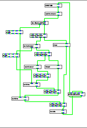
The Network Editor of AVS provides a visual interface for creating dataflow programs. For TESS, the dataflow is used to model the flow of air through the engine. Engine components (e.g., compressor, turbine, duct, etc.) are represented graphically as AVS module icons, or simply modules. Each module has a control panel where the operational characteristics of the engine component are defined by the user (e.g., the mass flow rate, design point performance data). An engine is created by selecting the modules needed and placing them in the work space of the Network Editor. The dataflow network is then created by connecting the modules to establish the physical connections of the engine. A typical TESS engine network that models a two spool, two stream turbofan engine is shown below.
Once all of the components have been connected and their operational parameters have been entered, the user selects the length of time for the transient, and defines how the governing equations are to be solved numerically for both the steady-state and transient portions of the simulation. Currently, for steady-state solutions, the user may choose either Newton-Raphson or Fourth-order Runge-Kutta methods. For transient solutions, the user may choose either Modified Euler, Fourth-order Runge-Kutta, Adams, or Gear methods. When simulation execution is begun, TESS first attempts to balance the engine at the initial operating point using the steady-state balancing method. Once the engine is balanced, the transient is begun and proceeds up to the number of simulation seconds defined by the user.
2.2.2 Advanced Ducted Propfan Analysis Code. The high-fidelity flow solver program used to model the operation of the fan component is the Advanced Ducted Propfan Analysis Code (ADPAC) [6]. ADPAC is a three-dimensional Euler/Navier-Stokes numerical analysis tool developed to study high-speed ducted propfan aircraft propulsion systems. The program utilizes a three-dimensional, time-marching numerical procedure along with a flexible, coupled 2-D/3-D multiple block geometric grid representation to predict the flow field in and around the fan. Multiple runs of ADPAC are needed to create the single-curve performance map used in the zooming strategy.
2.2.3 PVM. The parallel virtual machine (PVM) is a message-passing system that permits a network of heterogeneous Unix computers to be used as a single large parallel computer. Using PVM, a user-defined collection of different computers, known as the virtual machine, is used to provide aggregate power for solving large computational problems.
The PVM system is composed of a daemon which resides on all of the computers making up the virtual machine, and a library of PVM interface routines which supply user-callable routines. These functions, along with the PVM daemon, allow a PVM application on one computer to automatically start up tasks (computational processes) on other computers in the virtual machine and communicate data among the tasks by sending and receiving messages.
The prototype zooming system is defined by two suites of codes: The first suite, residing on the user's workstation, runs AVS and TESS. The second suite consists of ADPAC and associated codes [11]. One instance of this second suite exists for each of the multiple fan simulations used in the zooming strategy.
A new TESS engine component module, fan Multi-ADPAC, was created to provide the user interface and functionality for the zooming system. The module
- Handles the basic AVS data transfer for the fan component within TESS,
- Establishes the PVM virtual machine,
- Spawns the remote ADPAC tasks, and
- Controls the data transfer between TESS and the ADPAC simulations.
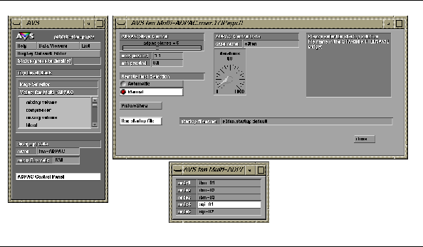
To utilize the fan Multi-ADPAC module in a TESS engine simulation, the user defines the ADPAC control parameters and the remote machines on which to spawn the ADPAC simulations. The AVS pop-up windows used to accept this input from the user are shown below.
PVM daemons are started on each remote machine specified by the user to create the virtual parallel machine.
Each time TESS needs fan performance data during a simulation, fan Multi-ADPAC creates the needed remote instances of ADPAC on the virtual machine and sends boundary condition parameters to each. fan Multi-ADPAC then waits for the simulation results. Each result is matched with its boundary conditions, then used to create data points on the performance curve (see Figure 2). Once all the values have been received, the performance curve is interpolated to match the stagnation pressure ratio across the fan, impressed by the TESS simulation, to determine the stagnation temperature ratio and mass flow rate. These values are then used by TESS to continue the complete propulsion system simulation.
The source code for ADPAC is maintained by a separate group at NASA Lewis Research Center, and has been unavailable for this project. As a result, the operation of each remote instance of ADPAC requires several codes, illustrated in the flow chart below.
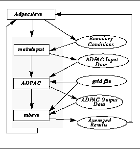
The first program, makeinput, creates the ADPAC input data file from the boundary parameters. Then, ADPAC executes, reading its grid file and the input data file. The output file produced by ADPAC is then read by the third program, mbave. This is a multi-block averaging program and integrates the three-dimensional flow solution to give the single (mass-averaged, lump) flow values which are needed by TESS. The adpacslave program coordinates the execution of the other three programs, and handles the PVM communications with fan Multi-ADPAC receiving the input data for makeinput and returning the results from mbave.
A new performance curve is created by fan Multi-ADPAC each time fan performance data is needed by TESS. To reduce the overall simulation time, the space-averaged values are retained and used to create an overall fan performance map. Before running flow solutions, this data is checked to see if the current operating conditions are within the data range. If so, the data is interpolated and used in the system simulation. In this manner, the simulation time may be significantly reduced. This also has the added benefit of creating an overall fan performance map which can be used in subsequent, non-zooming TESS simulations.
Engine Simulation: Intelligent Monitoring and Control
[Next] [Previous] [Top]
Generated with CERN WebMaker